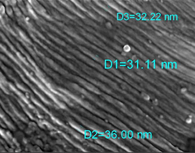
WEBINAR | From Infrastructure to Impact: EM & Micro-CT in Materials Core Facilities

Fracture in Focus: Mapping Fatigue in Ti-6Al-4V

High-resolution SEM reveals crack origin, propagation, and final failure in widely used titanium alloy.

hero
hero
Unlocked content

Every Crack Has a Beginning

Fatigue failure rarely announces itself. It starts as a microscopic imperfection, then travels silently across the material. In components made from titanium alloys like Ti-6Al-4V, even small cracks can lead to serious consequences. Understanding how and where that failure begins is the first step toward preventing it.

In this study, researchers used Tescan CLARA’s ultra-high-resolution SEM to investigate the full fracture surface of a fatigued Ti-6Al-4V sample. The imaging workflow captured the transition from crack initiation to propagation and final failure, giving engineers a direct look into the mechanics of material fatigue.

Why This Fractography

Workflow Works?

01
Root of the Problem

Seeing the Story Behind the Failure

Fatigue cracks do not form randomly. Their initiation and growth depend on the material’s structure and composition, loading conditions, and environmental factors such as corrosion. While both optical and conventional electron microscopes can face contrast and resolution limits, with UHR SEM you get to the finest details with great contrast. Understanding the cracking mechanism requires both an overall view of the fracture surface and high-resolution detail to reveal nanometer-scale striations.

To identify crack origins, track propagation paths, and understand how and where a part fails, researchers need a reliable, detail-rich imaging workflow.

02
Materials and Methods

SEM imaging strategy to trace fatigue failure across all fracture stages

The sample was a Ti-6Al-4V alloy component that failed under cyclic loading. Imaging was performed using a Tescan CLARA UHR SEM, with a focus on collecting clear data across three key regions:

01
Crack initiation point
02
Crack propagation zone
03
Final fracture area

Key technical elements:

  • Secondary electron imaging to highlight surface morphology

  • Wide Field Mode™ for broad overview and site selection

  • Variable magnification, with detailed imaging of features like striations and dimples

  • No coating or special prep needed

Each region was analyzed to identify telltale fracture patterns and to correlate visual features with the material’s response under stress.

03
Results and Discussion

Reading the Fracture in Layers

The initiation point of the crack shows typical crystallographic crack growth and fine striations, each marking a step in the fatigue cycle. In the propagation region, the presence, spacing, and orientation of striations revealed the direction and rate of crack growth and reflected the severity of the loading conditions. The measured striation spacing indicated the local crack propagation rate, and once the crack reached a critical length, a final fracture occurred, marked by ductile dimple formation and high plasticity at failure.

Because imaging was performed across scales and magnifications using Wide Field Mode™, researchers could study both the big picture and the fine detail. The clarity of striation patterns and dimple shapes confirmed that SEM fractography provides not just images, but insight.

This kind of analysis is invaluable for root-cause investigation, lifetime prediction, and materials development.

.

GET IN Touch

Contact us

Get the most out of Tescan

This is more than information; it's an advantage. We've compiled our technical whitepapers, detailed product flyers, and on-demand webinars to provide you with the knowledge that makes a real difference. Sign up now to access the insights you need to make an impact.

Tescan Instruments & Technology

Used in This Workflow

Tescan CLARA

Engineered to reveal surface detail on even the most challenging samples.

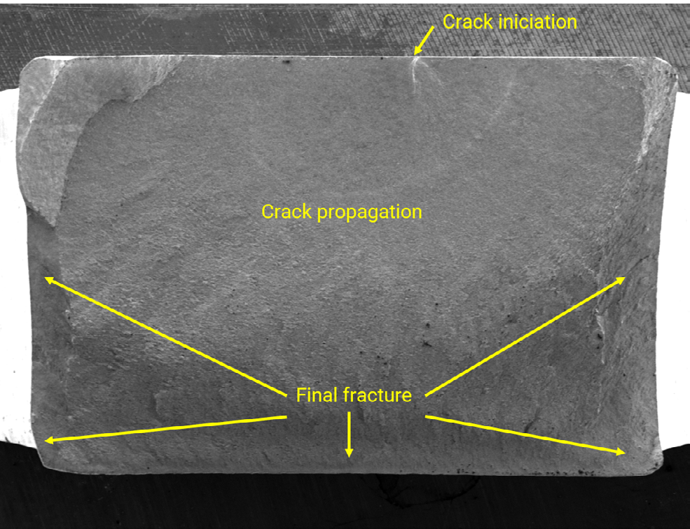
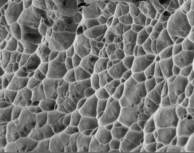
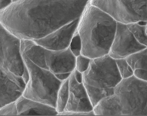
  • Rough, fractured surfaces in full details with high depth of focus

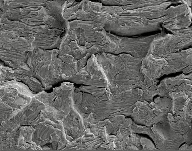
  • Produces high-contrast SE images with nanometer resolution

  • Low-kV capable for clear imaging of surface details

Wide Field™ Mode: Contextual Navigation Across the Sample

Overview imaging mode for full-sample observation, live navigation and seamless transition to high resolution.

  • Large area overview for live navigation

  • Image targeted features of interest without losing spatial reference

  • Especially useful for fracture surface analysis workflows

CLARA GM Mat. Science

GET IN Touch

Contact us

map

Where can you find us:

Tescan Brno
Libušina třída 21
623 00 Brno
Czech Republic

info@Tescan.com 

130405923 us US 37.09024 -95.712891 25.3575 29.349345 20.67957527 42.082797 39.91384763 -33.693421 13.93320106 3.039986586 31.997988 38.050985 47.579533 48.1485965 58.375799 54.663142 19.195447 56.975106 50.493053 45.868592 10.79556993 44.35660598 43.2371604 55.536415 14.557577179752773 32.100937 -6.116829 -6.212299277967318 23.7104 -33.471062 31.998740087 -23.69149395 43.462349 51.529848 49.1893523 49.197486 25.072375 31.075811 1.299027 40.676979 52.30150662 51.013813 35.684121 37.479653 52.246622 40.581349 39.911632 -26.1811371 41.818215 33.429928

No distributors found.